Build a Simple Circuit
The following circuit diagram turns on an LED when power is applied.
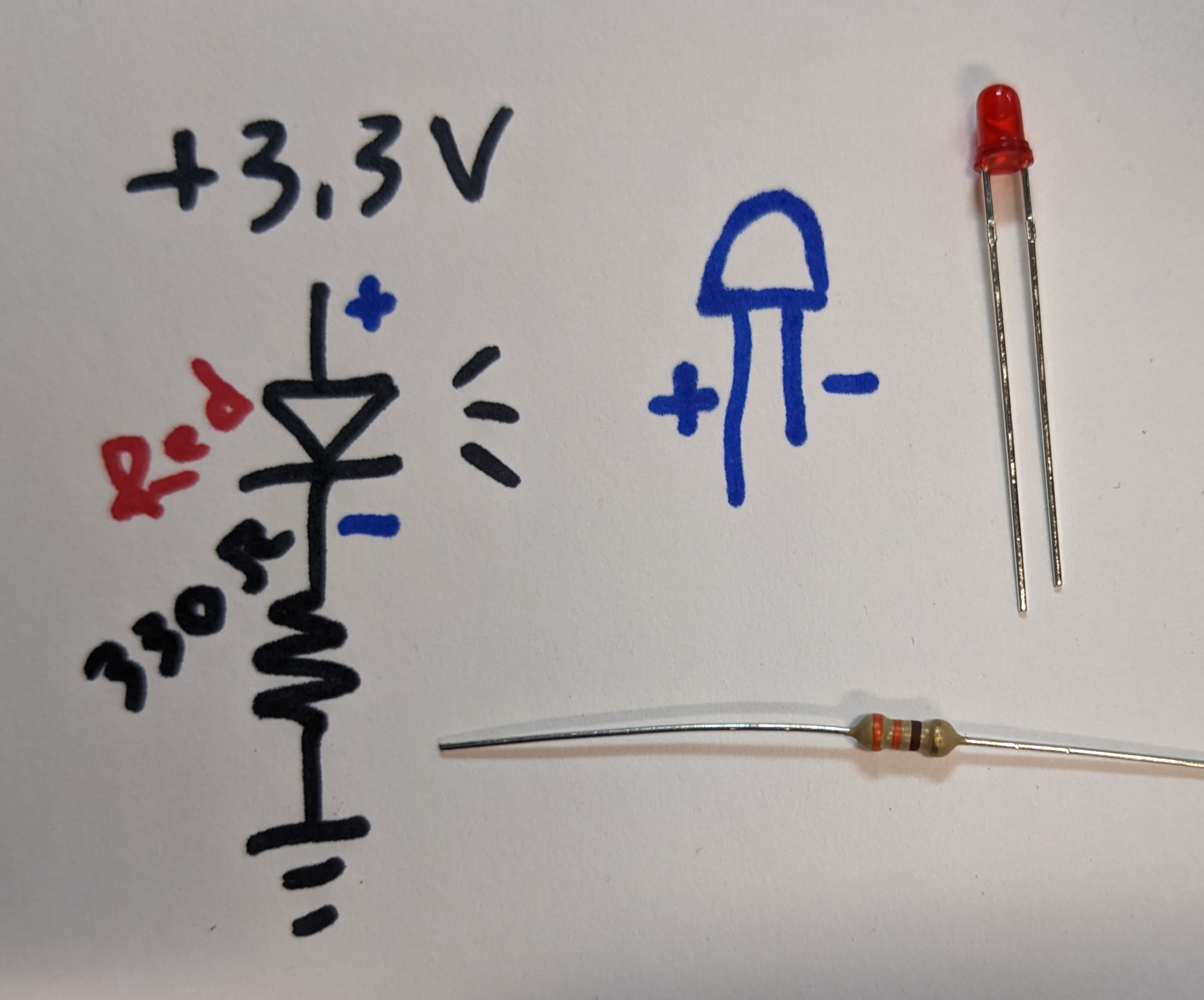
A light emitting diode (LED) will light up when a voltage above a minimum level is applied and several milliamps flow through. For most small, indicator type LEDs, the minimum voltage is about 1.7V, and 5mA makes the LED nice and visible. More than 10mA and the LED will get hot and possibly start to smoke. Current can flow through the LED in one way, in the direction of the arrow. If the LED is inserted backwards it will not light! This type of component is called polarized, since it only works one way. Most polarized components have a long leg and a short leg, where the longer leg is the more positive side, to indicate how to plug it in.
A resistor follows Ohm's Law, V = I * R. It would be difficult to make the exact voltage the LED requires to turn on the LED, so a larger voltage is applied, the LED uses up what it needs to turn on, and the remaining volage ends up across the resistor. In this way the current through the circuit is controlled, by using Ohm's Law with the remaining voltage, to select a resistor to generate the required current. Resistors are not polarized, so they can be plugged in either way. Resistors have color bands to indicate their value, or a multimeter in resistance mode can be used to read the value.
Values are read with the gold band on the right, as [color1 color2 * 10 to the color3]. For example, brown black orange gold is 1 0 * 10^3, or 10k Ohms.
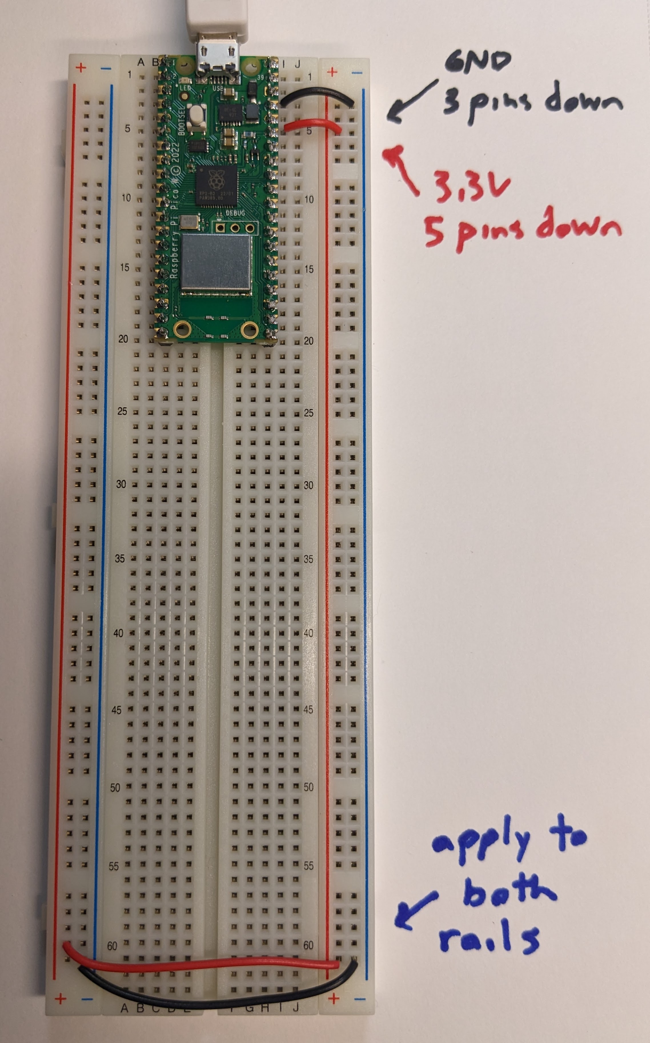
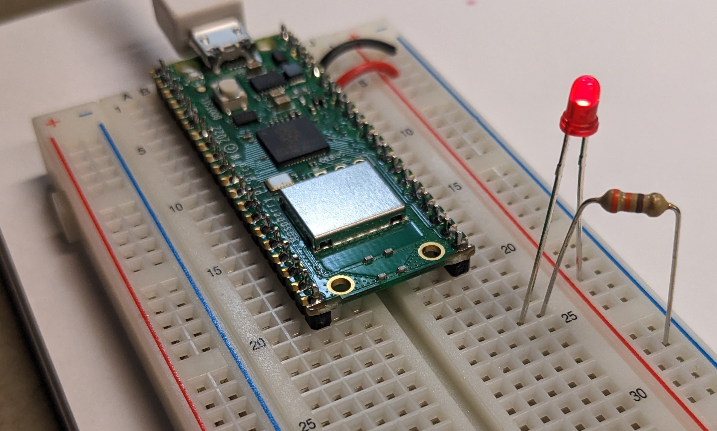
Power for this circuit is provided by 3.3V. Current flows from more positive voltage (3.3V) to less positive voltage (0V, also called ground or GND). For this circuit, we will use a Raspberry Pi Pico to generate 3.3V. The Pico recieves 5V from the USB cable and converts it to 3.3V for us to use. The Pico, plugged into the breadboard, has several pins that are GND, and one pin that is 3.3V, called 3V3(OUT). The pins on the Pico are not labelled, so you'll need an image of the pinout for a Raspberry Pi Pico, like the Pico 2W (all the Pico pinouts are the same):

Most subcircuits in a design need access to power and ground, so the breadboard rails are usually connected to provide large numbers of connection points up and down the breadboard for ease of use.
Get power into the rails
Make a red wire to connect 3V3(OUT) to the red rail of the breadboard. Make a black wire to connect one of the GND pins to the blue rail of the breadboard. Make a pair of red and black wires to connect the opposite sides of the breadboard to each other.
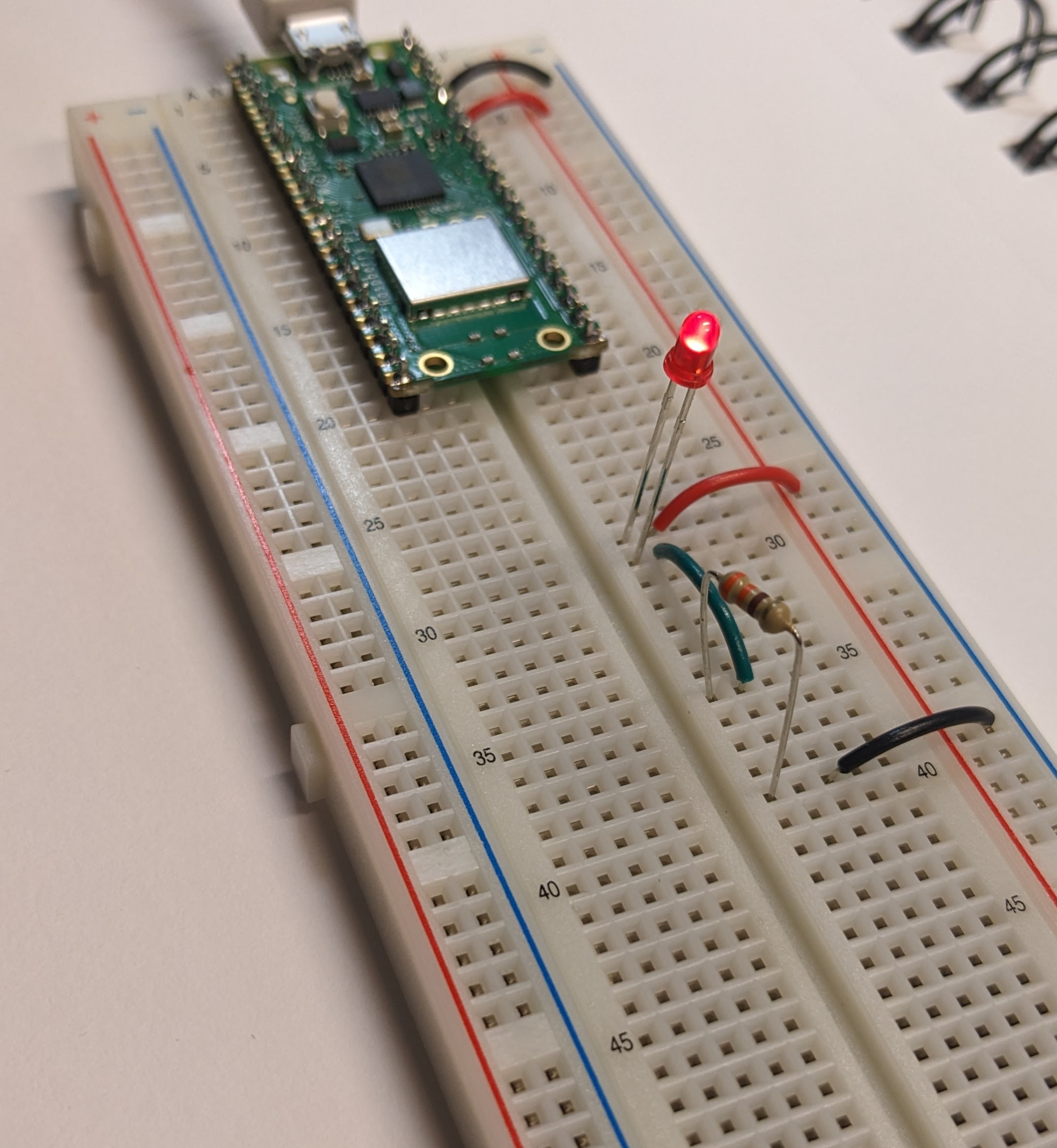
Build the circuit
Follow the circuit diagram to light up the LED. Start at 3.3V to the long side of the LED, the short side of the LED touches the resistor, and the other side of the resistor touches GND. There are an infinite number of ways to construct the circuit on the breadboard! Use red wires for 3.3V connections, black wires for GND connections, and other colors for intermediate steps. Here is one way to build the circuit:
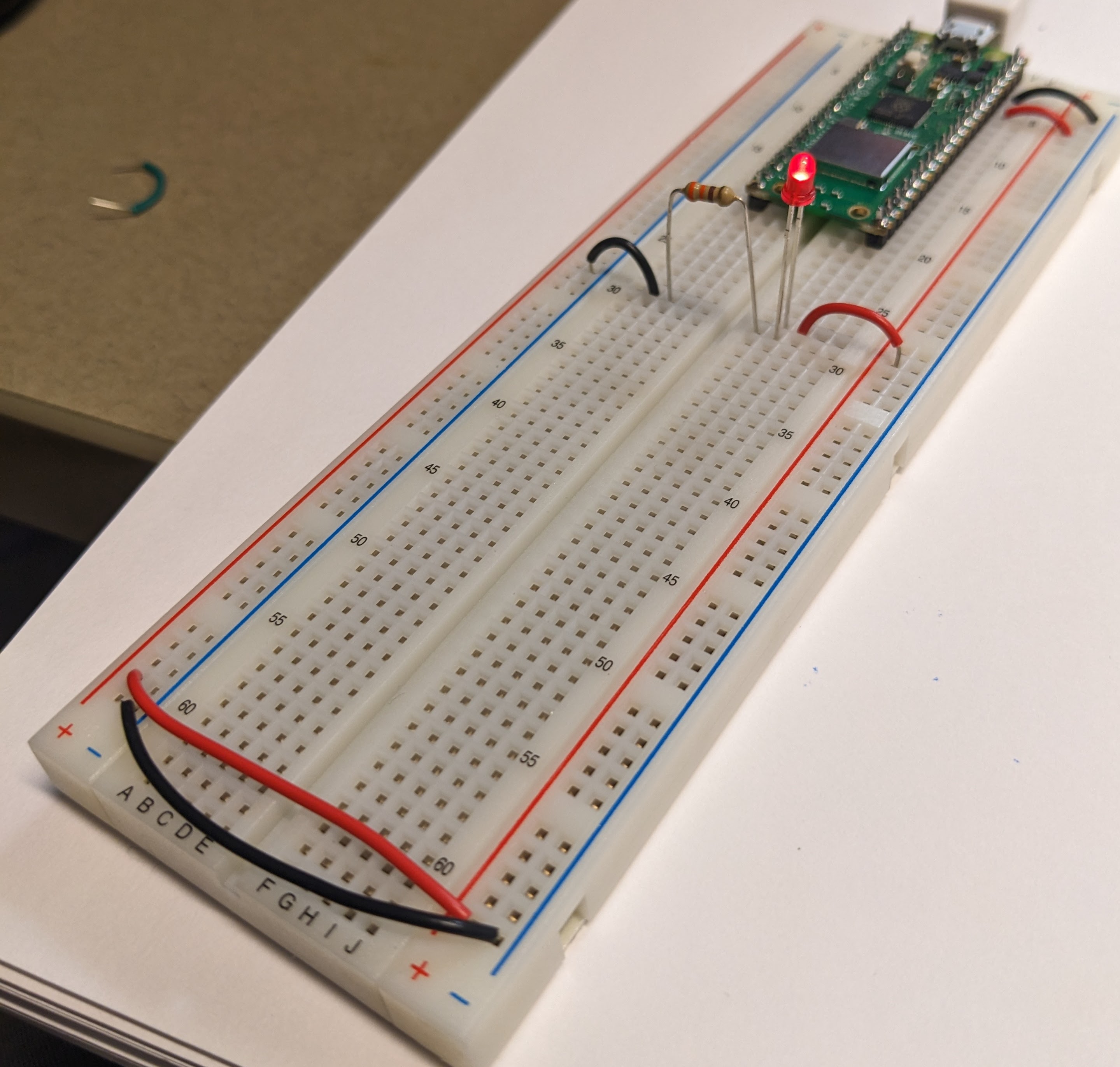
Here is a method that uses no wires:
Here is a method that spans the breadboard:
Everyone will have a different physical layout after building the circuit, but the circuit diagram is the same. This is why we work from circuit diagram, not by showing images of breadboards.
Edit the circuit
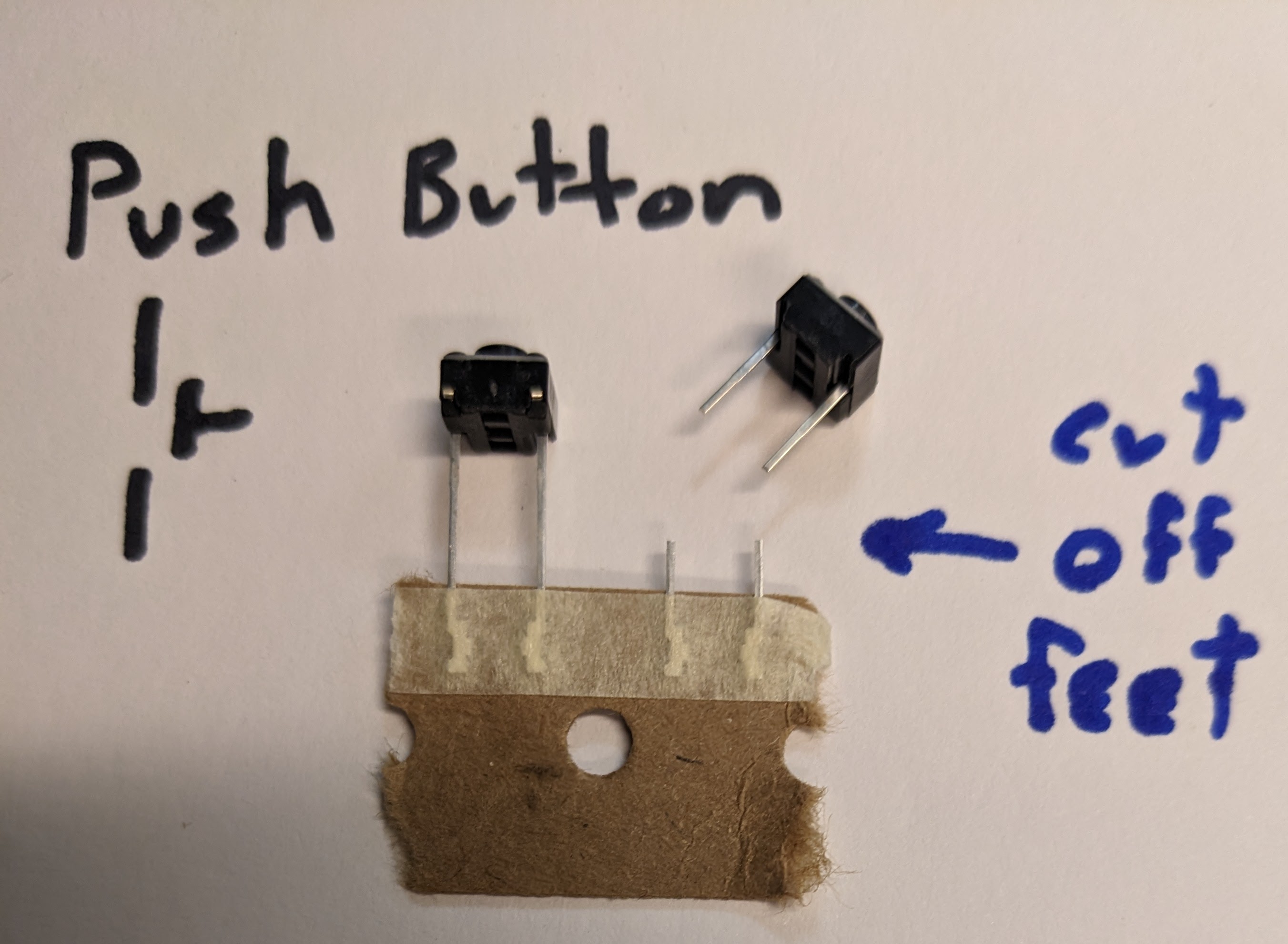
A push button is a wire that is not continuous until the button plunger is pressed. Sometimes buttons come from the manufacturer in a cardboard strip with flat feet to keep them from falling out of the cardboard, so if your buttons have those feet, cut them off so they don't get stuck in the breadboard.
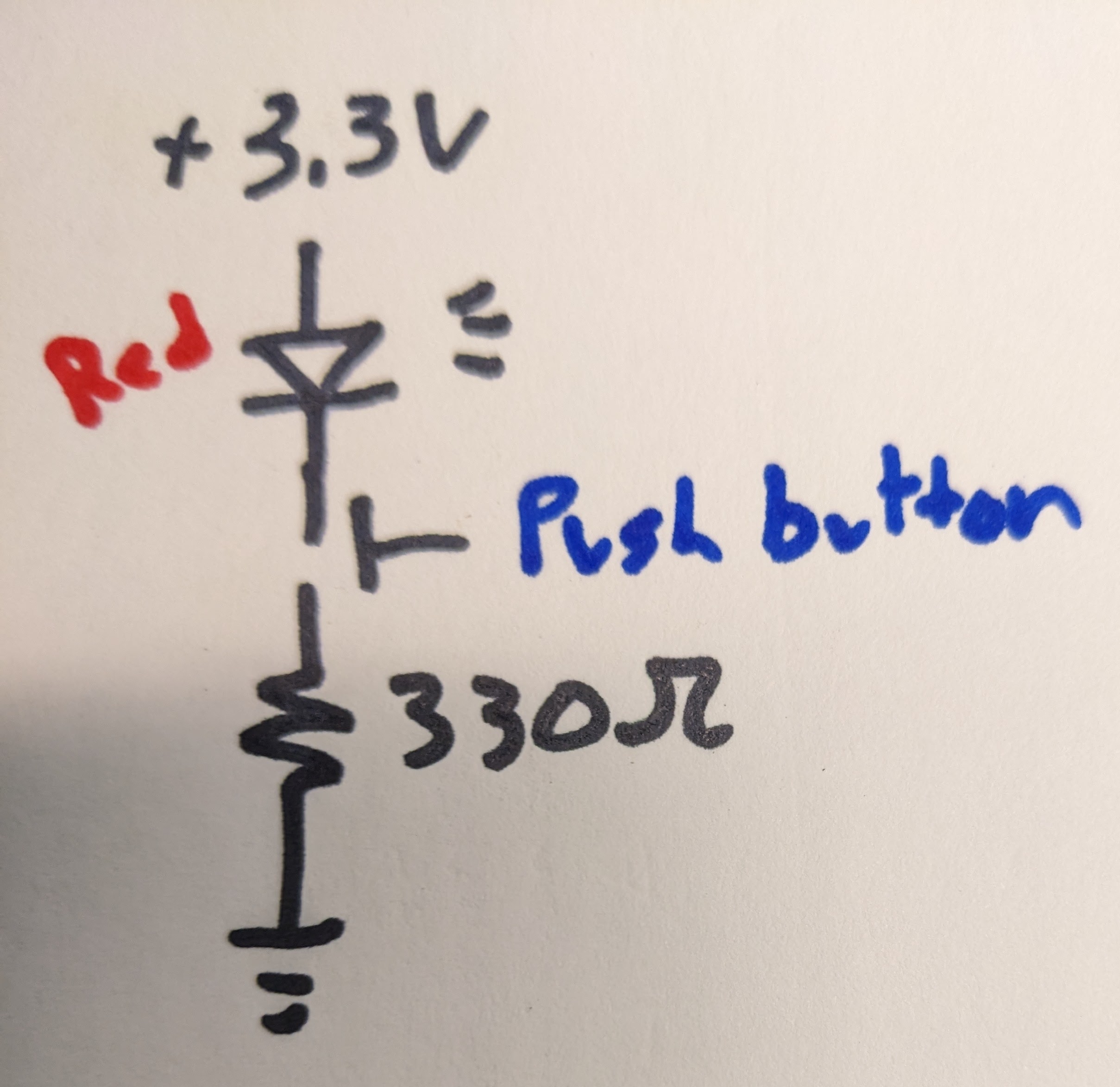
The button is drawn like a wire with a plunger. Insert it into your LED circuit according to this circuit diagram:
When you press the button, the LED should light up! Good questions to consider here are:
- does the order of the components matter for this circuit?
- how could I redesign the circuit diagram so that the LED is always on and pressing the button turns it off?
- how could I edit the circuit diagram to turn on several LEDs or change the brightness of the LEDs?
Safety
Your intuition might be warning you that you are touching wires that have voltages on them and current through them, and that is not safe to do in most situations. Also, you can accidentally short the power supply while building the circuit, which is like shorting your USB port.
The best practice is to unplug your power supply while building the circuit, and double check what you have built before plugging back in. This will help protect your computer, and prevent you from touching any live circuit. Following color coded wire conventions will help with visual inspections of the circuit.
Your computer's USB port also has over current protection, so if you do short the USB, the computer will disable the port to protect itself. If you notice your port is not working, rebooting your computer will reenable it. The USB port does not have over voltage protection, so take a lot of care when using an external power supply (like a battery) in addition to a USB port.
For your own personal safety considerations, it would take several mA through your chest to stop your heart. Your skin is usually > 100k Ohm, so you would need to touch a large voltage,like from the AC wall outlet, to shock yourself in a dangerous way. 3.3V, 5V and 12V projects are generally safe to touch. If you are ever unsure, put one hand in your pocket while working, so that in the event of a shock, the current cannot travel from one hand to the other through your chest. Touching a live wire can cause your muscles to contract, so if you must touch a conductor (like an electric horse fence) touch with the back of your hand so that you do not clamp down on the wire.