Programming the Pico in Circuit Python
The Raspberry Pi Pico microcontroller breakout board is a powerful and inexpensive device that can be programmed in Circuit Python or in C. On this page, we will program it with Cicruit Python.
When the Pico is plugged into a computer for the first time it will enumerate as a thumb drive called RPI-RP2 (Pico 1) or RP2350 (Pico 2). This is the default, blank configuration of the board. The board can be placed into this mode while holding the BOOT button while plugging the USB cable in.
To install Circuit Python, download a precompiled version from the Circuit Python website for your specific board (Pico 1, Pico 1 W, Pico 2, etc). Copy the file with a .uf2 extension onto the drive. The drive will dissappear and then reappear as a new thumb drive called CIRCUITPY. On this drive is a file called code.py, a folder called lib, and two other text files.
To edit the code, open code.py in a text editor, edit the file, and after clicking save, the new file will start to run. The board will also enumerate as a virtual serial port, and the port can be opened in a terminal emulation program to send and recieve data.
After the code is saved, it will remain on the board forever. Unplug the USB and plug in a battery and the code will immediately begin running again! The code doesn't really end either, typically the code will loop forever, until power is removed.
You will need two programs to interact with the Pico - a text editor, and a terminal emulator program. Many text editors will work, I suggest VSCode. For a terminal emulator, if you are on Windows, download and install Putty. If you are on Mac, you already have a program called Screen for this purpose.
Open VSCode, and go to File->Open Folder, and select CIRCUITPY. Then, on the right file tree, open code.py. This is the file that lives on the Pico, and saving it will run the code.
One downside to the design of the Circuit Python system is that the code that runs on the board must be named code.py. If there is no file called code.py then nothing will run, and putting another .py file in the drive will be ignored unless it is run as a function from code.py. Not a horrible problem, but annoying when you have a few different programs to try out and you must constantly rename them.
REPL
Before editing code.py we can interact with Circuit Python using Read-Evaluate-Print-Loop, or REPL mode. REPL mode uses your computer screen to display the data from the Pico, and your computer keyboard to send data to the Pico.
First, you need to find the name of your Pico's USB port. Then, open the port on the terminal emulator program.
On Windows, open the program Device Manager, and scroll down to PORTS. The name of the Pico should be something like COM3. Open the program Putty, and select the Serial radio button. Enter the name of the port and click Open.
On Mac, open the program Terminal. To list the names of the USB devices available, type ls /dev/tty.*. The Pico will be something like /dev/tty.usbmodem1234. Now, type screen /dev/tty.usbmodem1234, and the screen will clear as the program Screen runs inside it. Later, to exit Screen, don't close the Terminal program, instead type control-a control-k followed by "y" (this is the appropriate way to close the Screen program). If you do close Terminal without closing Screen, you will need to unplug and replug the Pico to free the port.
In the terminal emulator, type any key and the board will enter REPL mode and present three carrots, ">>>". This is your clue that you can now interact directly with Python.
In REPL mode you can create variables, do math or loops, and test code snippets. You wouldn't want to work in REPL, it is too slow to add the code. Saving code in a file is much more convinient, but REPL is useful for debugging.
To exit REPL and run code.py, type "control-d". If the code ends, the terminal emulator will prompt you to type any key to enter REPL or type "control-d" to run the code again. Usually the code is in an infinite loop and will not end, so to cause the code to end and enter REPL at any time you can type "control-c". This is the best way to stop and restart the code.
Try some code!
Hello World!
import time # get the sleep function

print("Hello World!") # print something!
i = 0 # a variable

# loop forever
while True:
    print("i = " + str(i)) # combine a variable and a string
    i = i + 1
    time.sleep(1) # wait 1 second
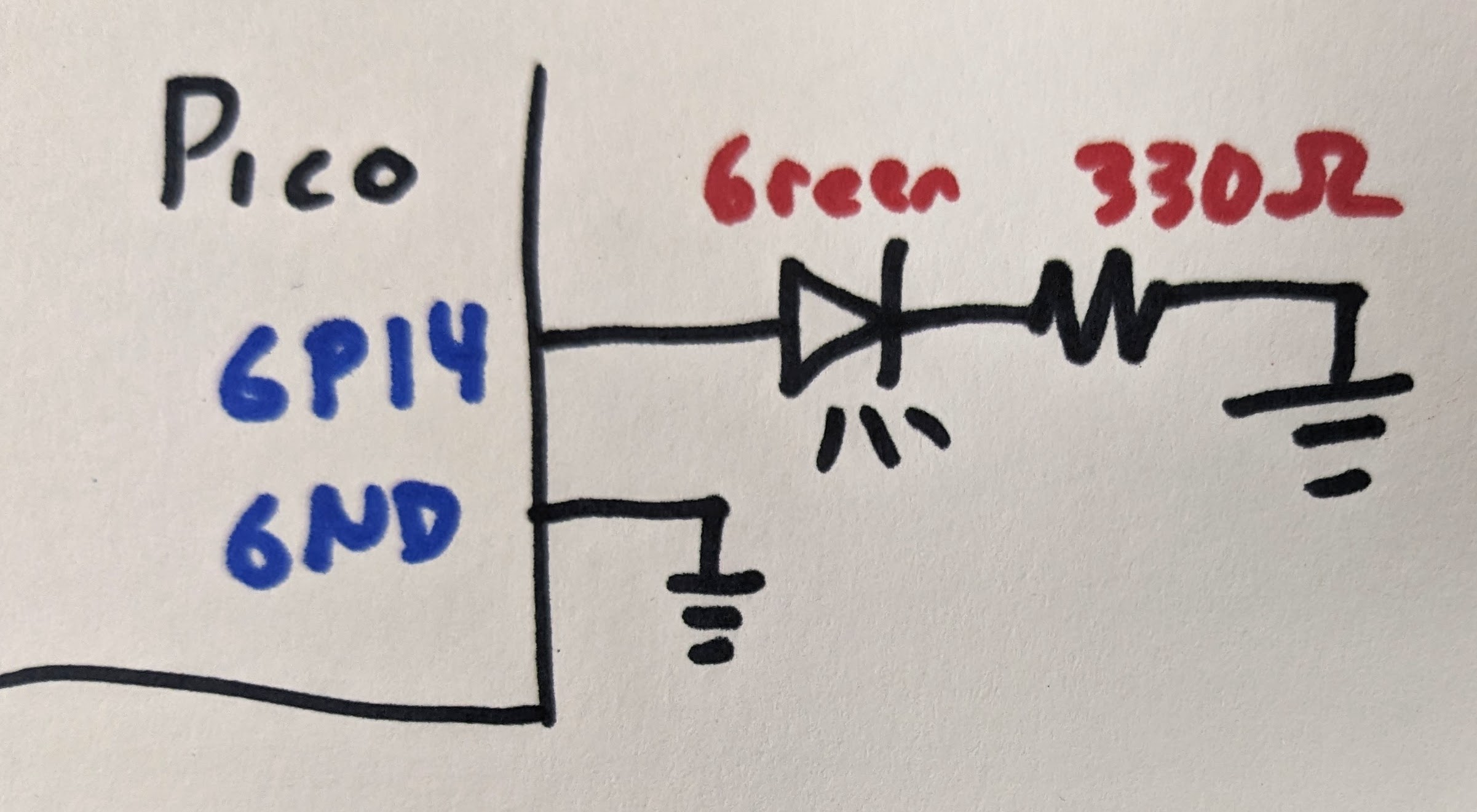
Blink an LED
import board # the pin definitions
import time
import digitalio # get access to digital pins

# make pin GP14 a digital output
greenled = digitalio.DigitalInOut(board.GP14)
greenled.direction = digitalio.Direction.OUTPUT

# build a LED circuit form GP14 to GND
while 1:
    greenled.value = 1 # turn on the LED
    time.sleep(.1) # wait
    greenled.value = 0 # turn off the LED
    time.sleep(.1) # wait
Change LED brightness with PWM
Pulse width modulation, or PWM, blinks a pin at a frequency so fast that your eye smooths out the blinking, and the duty cycle sets how bright the LED appears to be.
All GPIO pins can generate PWM, but there are only 16 PWM channels, so you cannot assign two independent PWM pins to the same channel. The channels are shown in the following table from the RP2040 datasheet:
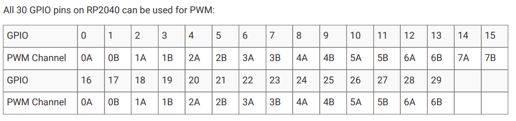
For example, you can use PWM on GP13 and GP14, but not GP14 and GP15.
import board
import pwmio # get access to PWM
import time

# control GP14 with PWM
led = pwmio.PWMOut(board.GP14, variable_frequency=True)
led.frequency = 500 # in hz
led.duty_cycle = 0 # initially off, at 16bit number so max on is 65535

while True:
    # start duty cycle at 0, every loop increase by 100
    # until getting to the max of 65535
    for i in range(0, 65535, 100):
        led.duty_cycle = i
        time.sleep(0.01)
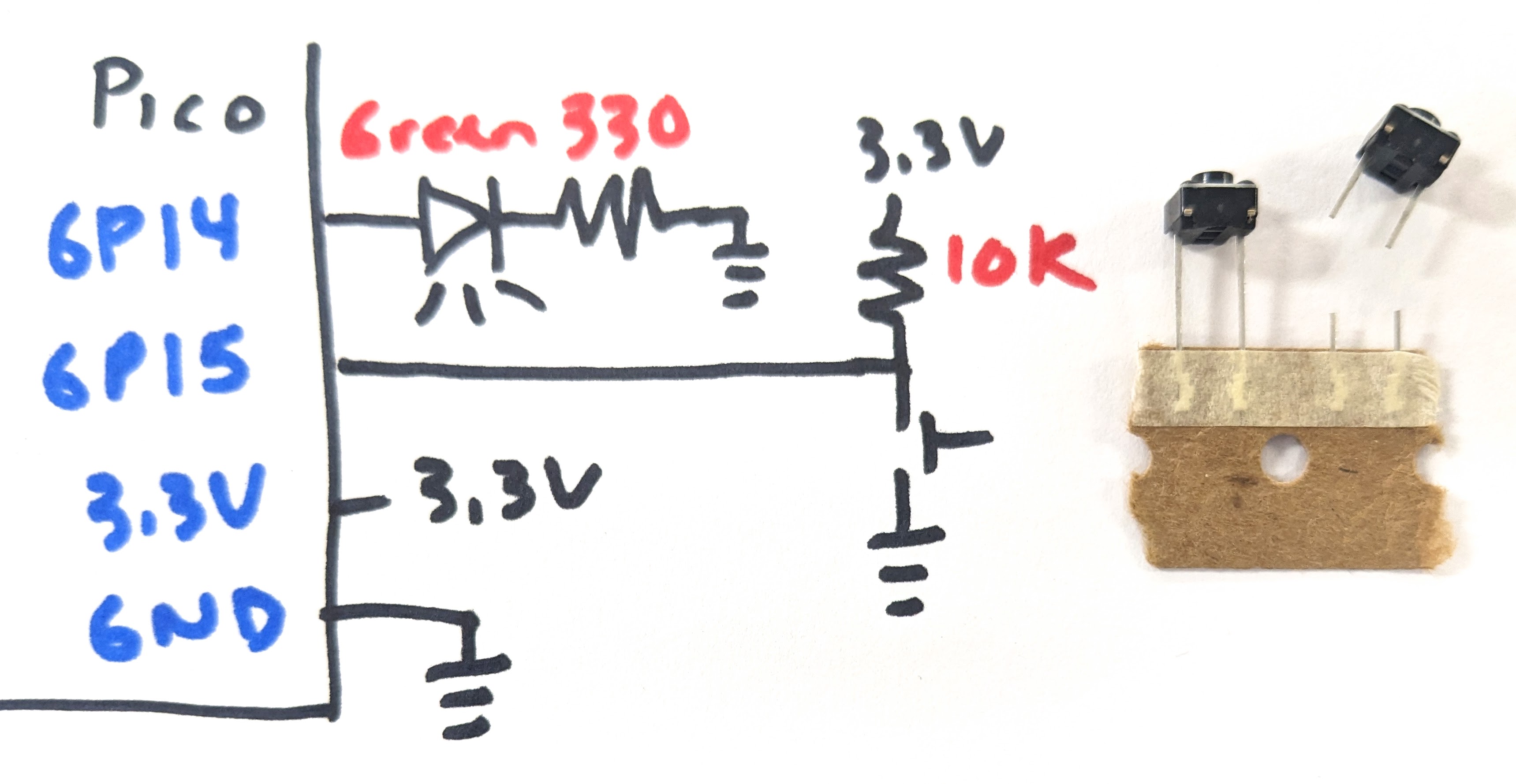
Read a push button
import board
import time
import digitalio

# an LED on GP14, set as an output pin
greenled = digitalio.DigitalInOut(board.GP14)
greenled.direction = digitalio.Direction.OUTPUT

# a push button circuit on GP15, set as an input pin
buttonpin = digitalio.DigitalInOut(board.GP15)
buttonpin.direction = digitalio.Direction.INPUT

while 1:
    if buttonpin.value == 0:
        greenled.value = 1
        print("On!")
    else:
        greenled.value = 0
        print("off")
    # if printing, slow down the code to less than 100Hz
    # or your computer screen will struggle to show all the prints
    time.sleep(0.05) # 20 times per second
Button Debounce
The voltage from a button press can toggle very quickly with one button press. The "bounces" can be ignored by reading the button after detecting a press and making sure the button is still pressed a short time later.
import board
import time
import digitalio

greenled = digitalio.DigitalInOut(board.GP14)
greenled.direction = digitalio.Direction.OUTPUT

buttonpin = digitalio.DigitalInOut(board.GP15)
buttonpin.direction = digitalio.Direction.INPUT

# global variables
buttonprevious = 1 # the default state of the button is 1
greenledstate = 0 # the initial state of the LED
buttonpressedcount = 0 # how many times the button has been pressed

while 1:
    # if the button vlaue changed from hight to low
    # this is the moment the button is pressed
    if buttonpin.value == 0 and buttonprevious == 1:
        # IMPLEMENT
        # wait a small amount of time and see if the button is still pressed
        # then:

        # change the state of the LED
        if greenledstate == 0:
            greenledstate = 1
        else:
            greenledstate = 0
        # add one to the number of times the button was pressed
        buttonpressedcount = buttonpressedcount + 1
        print(str(buttonpressedcount))

    # remember the button state for next time and set the LED
    buttonprevious = buttonpin.value
    greenled.value = greenledstate
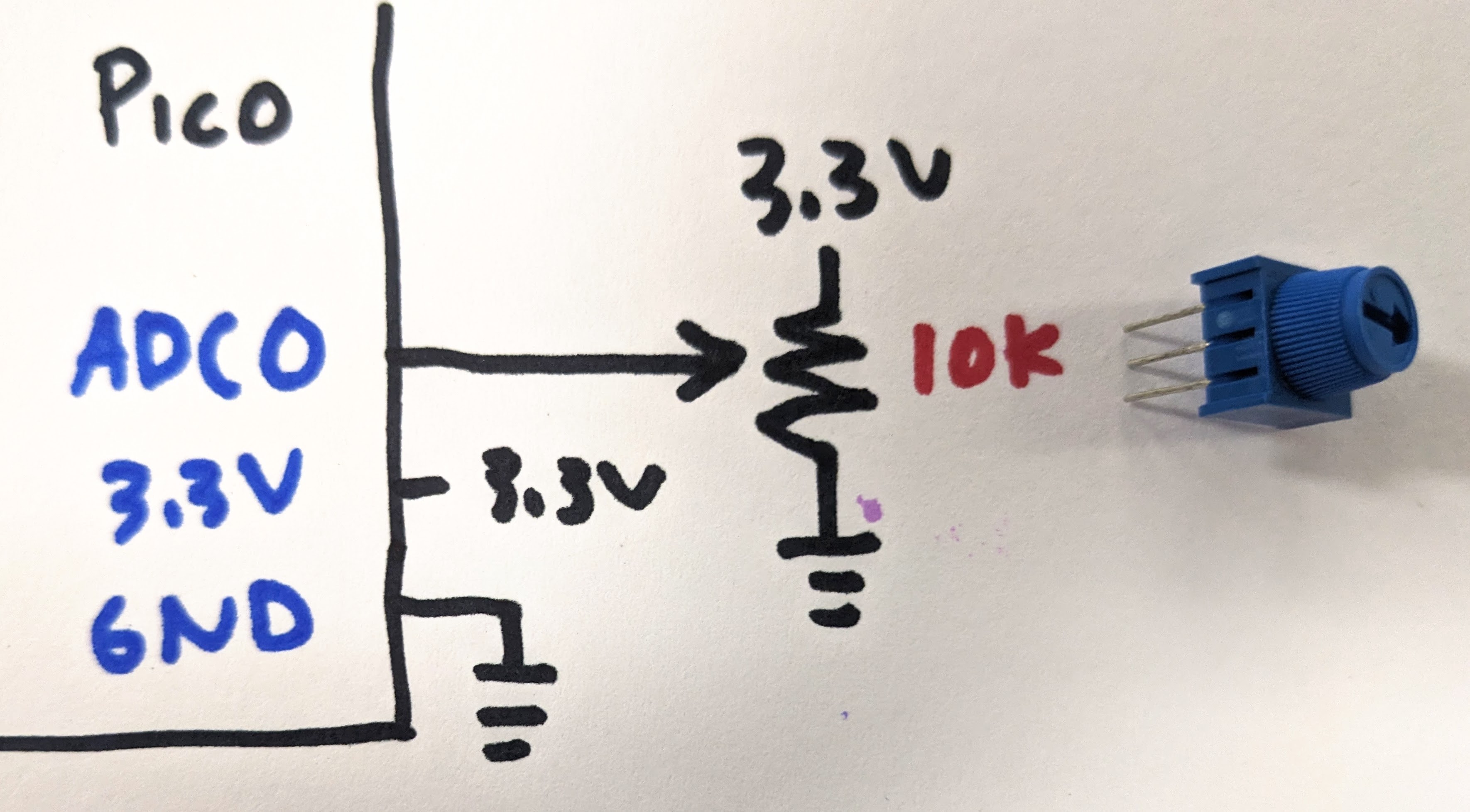
Read an analog voltage
The analog to digital converter, or ADC, converts 0-3.3V to digital values from 0-65535.
import board
import time
from analogio import AnalogIn # get access to analog pins

potentiometerpin = AnalogIn(board.A0) # on the Pico there are only 3 pins!

while 1:
    # the analog converter returns 0 for 0V, 65535 for 3.3V
    print(potentiometerpin.value)
    time.sleep(.1) # 10 times per second

    # or try these lines to format for the Plotter tool in Mu
    #volt = 3.3 * potentiometerpin.value / 65535
    #print("(" + str(volt) + ",)")
    #time.sleep(.1) # 10 times per second
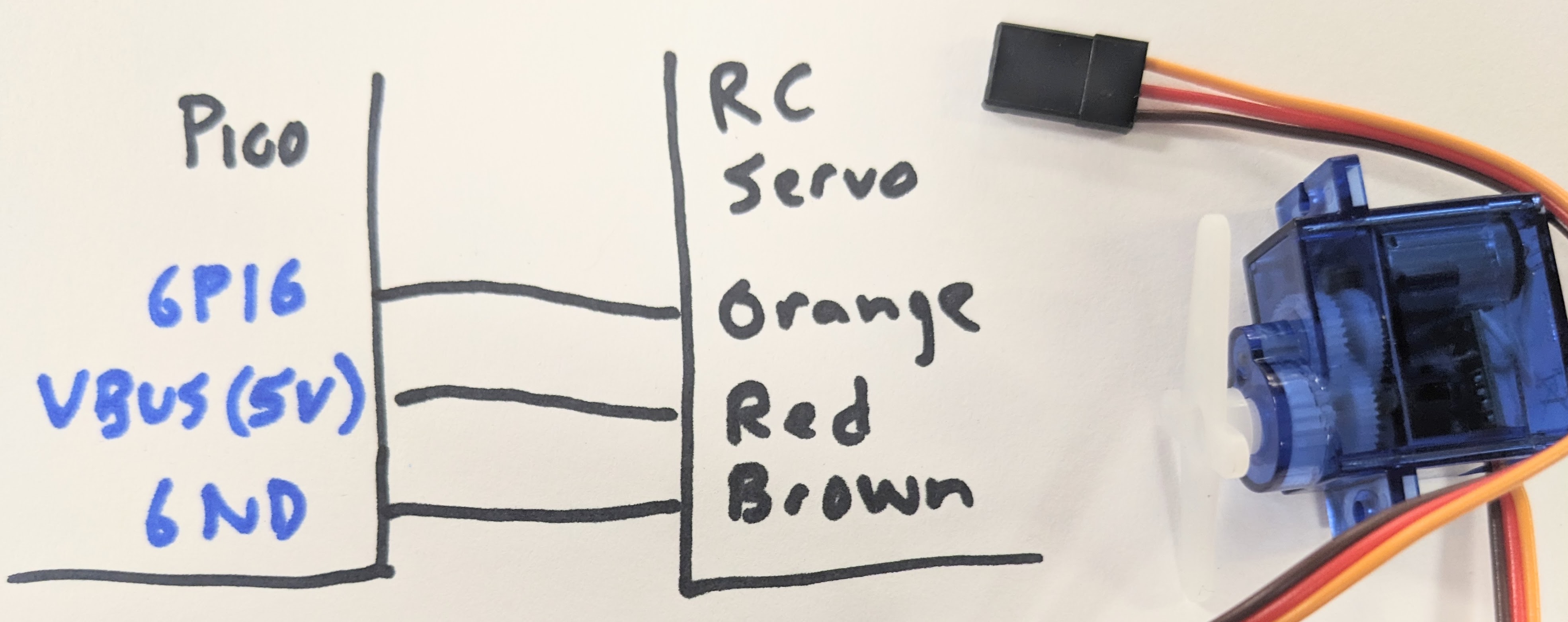
Set the angle of an RC servo motor
An RC servo motor is a position controlled device. The cable requires 4-6V on the red wire, ground on the brown wire, and a digital signal on the orange wire. The digital signal is a pulse, 0.5 ms to command 0 degrees to 2.5 ms to command 180 degrees, every 20 ms. This can be acheived with PWM.
import board
import pwmio
import time

# there are other libraries for controlling RC servo motors
# but really all you need is PWM at 50Hz
servo = pwmio.PWMOut(board.GP16, variable_frequency=True)
servo.frequency = 50 # hz

while True:
    # pulse 0.5 ms to 2.5 ms out of a possible 20 ms (50Hz)
    # for 0 degrees to 180 degrees
    # so duty_cycle can be 65535*0.5/20 to 65535*2.5/20
    # but check this, some servo brands might only want 1-2 ms

    # command the servo to move from 0 to 180 degrees
    for i in range(int(65535*0.5/20), int(65535*2.5/20), 100):
        servo.duty_cycle = i
        time.sleep(0.1)
Play a sound file with PWM and an analog amp
The Pico can play audio files saved in the .wav format, using PWM to create the analog sound signal. The signal can go straight to a small speaker for a quiet sound, or go to an audio amplifier like this to be quite loud. Sound files can be found online in free repositories like here or you can make your own with free audio software like Audacity or REAPER. Note that the Pico board has limited memory, less than 1MB available, so the files must be small. You can use Audacity to downsample the file to a lower sample rate, but the audio quality might be compromised. The audio amplifier works best with a 5V supply, and a large capacitor from Power+ to Power- helps remove hiss. The speaker goes between the Out + and - pins, the G pin goes to ground, and the audio signal goes to the L or B (looks like a typo on the board, should be R) pins.
import board
import time
import audiocore
import audiopwmio
import digitalio

# a push button circuit on GP15, set as an input pin
buttonpin = digitalio.DigitalInOut(board.GP15)
buttonpin.direction = digitalio.Direction.INPUT
buttonpin.pull = digitalio.Pull.UP # simplify the button circuit
# load the sound files into variables
sound1 = open("cash_register.wav", "rb")
sound2 = open("applause.wav", "rb")
# prepare the sound files to play
wav1 = audiocore.WaveFile(sound1)
wav2 = audiocore.WaveFile(sound2)
# set the pin to play sound from
a = audiopwmio.PWMAudioOut(board.GP16)
# button state variables
times_pressed = 0
button = 1
old_button = 1

while 1:
    button = buttonpin.value
    if (button == 0 and old_button == 1):
        if (times_pressed == 0):
            print("0")
            a.play(wav1) # play the sound
            while a.playing:
                time.sleep(.01)
            times_pressed = 1
        elif (times_pressed == 1):
            print("1")
            a.play(wav2) # play the sound
            while a.playing:
                time.sleep(.01)
            times_pressed = 0
    old_button = button
Set the color of an addressable RGB LED (Neopixel or ws2812b)
LEDs can be PWMed to change their brightness, and you can use combined red/green/blue LEDs in a single package to make any color, but each LED would require 3 PWM pins. You just don't have enough pins to control a lot of LEDs.
How many is a lot? Maybe you want hundreds of LEDs. You can do this with "smart" LEDs like the ws2812b, also known as Neopixels. Each LED color and brightness can be set individually with just one pin from the microcontroller.
The following method is a very simple way to set the color of a single Neopixel. Further down on this page you'll see a method that uses an external library and allows for more high level control of many LED colors, but this simple method is included in the default version of Circuit Python. How can you find these included functions? In REPL mode, type "import [tab key]", and all the available methods will be printed.
![]()
import board
import neopixel_write # a simple method for setting a neopixel color
import digitalio
import time

# connect the pin to the neopixel DIN
pin = digitalio.DigitalInOut(board.GP13)
pin.direction = digitalio.Direction.OUTPUT

pixel_off = bytearray([0, 0, 0]) # R,G,B value, 0 for off, 255 for full on
red = bytearray([255,0,0])
green = bytearray([0,255,0])
blue = bytearray([0,0,255])
neopixel_write.neopixel_write(pin, pixel_off)

while True:
    neopixel_write.neopixel_write(pin, red)
    time.sleep(1)
    neopixel_write.neopixel_write(pin, green)
    time.sleep(1)
    neopixel_write.neopixel_write(pin, blue)
    time.sleep(1)
Code with external libraries
Most complicated components that you connect to your board with a circuit do not have code included with Circuit Python. The library must be downloaded and copied to the CIRCUITPY/lib folder to work. There isn't enough space on the board for all of the libraries, only copy the libraries you need!
The libraries come as a zip folder from Circuit Python. Download the folder that corresponds to your version of Circuit Python and unzip the folder. Libraries are found in the library bundle /lib folder, sometimes as files with .mpy extensions or as entire folders. Copy the files needed into the CIRCUITPY/lib folder. Note the Pico has limited space, so copy only the files you need. Example code is found in the library bundle /examples folder, the contents of these files can be copied into code.py. Remeber that the code that runs on your board is code.py, so you can't just copy an example .py file, it must be named code.py!
Advanced neopixel control
Find the neopixel.mpy file in the library bundle lib folder (/lib/neopixel.p, one of the few files that does not start with adafruit_) and copy it to CIRCUITPY/lib.
The function
pixels = neopixel.NeoPixel()
creates a structure that allows access the color of each LED in the Neopixel strip. For example, the first Neopixel is at index 0:
pixels[0] = (255,0,0) # set the first LED full red
Nothing happens at that moment. All of the Neopixels update simultaneously when you call the show function
pixels.show()
![]()
import time
import board
import neopixel # copy neopixel.mpy from library bundle into CIRCUITPY/lib

din_pin = board.GP17 # the pin connected to the neopixel DIN
num_pixels = 8 # how many neopixels in the strip

ORDER = neopixel.GRB # sometimes a strip is RGB, depends on the manufacturer

# make a variable to represent all the pixel LEDs
# neopixels are painfully bright, the brightness setting scales them to not be too powerful
pixels = neopixel.NeoPixel(din_pin, num_pixels, brightness=0.2, auto_write=False, pixel_order=ORDER)

pixels.fill((0, 0, 0)) # set the value of every pixel to off
pixels.show() # send the values to the strip, this function must be called to make the colors appear

while True:
    pixels.fill((0, 255, 0)) # set every pixel to green
    pixels.show()
    time.sleep(1)

    pixels.fill((0, 0, 0)) # set every pixel to off
    pixels[0] = (255,0,0) # first pixel to red
    pixels[1] = (0,255,0) # second pixel to green
    pixels[2] = (0,0,255) # third pixel to blue
    pixels.show()
    time.sleep(1)
The following code sets each Neopixel to the same brightness according to a color on the color wheel, so the input is a single number from 0 to 360 and the output is in RGB, starting at red. This is a useful function because the brightness is constant and it takes only one input.
# color functions from Adafruit
# fade pixels through all colors of the rainbow

import time
import board
import neopixel

din_pin = board.GP17
num_pixels = 8
ORDER = neopixel.GRB
pixels = neopixel.NeoPixel(din_pin, num_pixels, brightness=0.2, auto_write=False, pixel_order=ORDER)

def wheel(pos):
    # Input a value 0 to 255 to get a color value.
    # The colours are a transition r - g - b - back to r.
    if pos < 0 or pos > 255:
        r = g = b = 0
    elif pos < 85:
        r = int(pos * 3)
        g = int(255 - pos * 3)
        b = 0
    elif pos < 170:
        pos -= 85
        r = int(255 - pos * 3)
        g = 0
        b = int(pos * 3)
    else:
        pos -= 170
        r = 0
        g = int(pos * 3)
        b = int(255 - pos * 3)
    return (r, g, b) if ORDER in (neopixel.RGB, neopixel.GRB) else (r, g, b, 0)

def rainbow_cycle(wait):
    for j in range(255):
        for i in range(num_pixels):
            pixel_index = (i * 256 // num_pixels) + j
            pixels[i] = wheel(pixel_index & 255)
        pixels.show()
        time.sleep(wait)

while True:
    rainbow_cycle(0.01)  # rainbow cycle with 10ms delay per step
Read an accelerometer
An accelerometer reports the acceleration of the board along the X, Y and Z axes. Acceleration is measured in Gs. At rest with Z pointed up, X and Y will report 0 G and Z will report -1 G. Sometimes the data is an integer and you must convert to Gs knowing the sensitivity and resolution of the accelerometer.
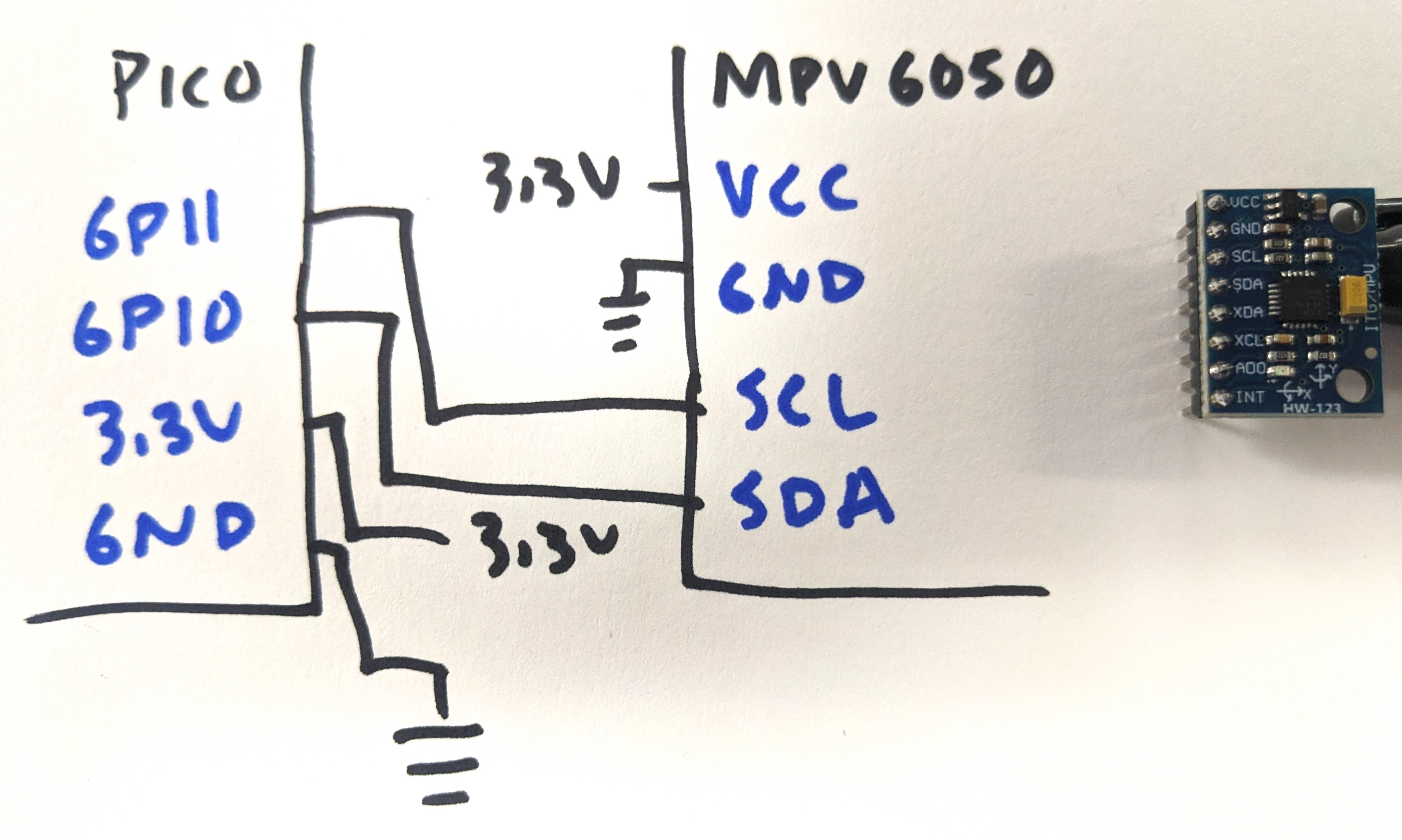
Read an IMU
An intertial measurement unit reports at least acceleration and angular velocity, and sometimes also magnetic field strength and barometric pressure. All of this raw data can be integrated to estimate position and orientation, although the algorithm can be tricky and the sensor needs to be low noise, low offset and low drift.
# read acceleration and angular velocity from the MPU6050 IMU
import time
import board
import busio
#import adafruit_register
import adafruit_mpu6050 # required the adafruit_register library folder to be in CIRCUITPY/lib/

i2c = busio.I2C(board.GP11, board.GP10) # the I2C pins used, (SCL, SDA)
mpu = adafruit_mpu6050.MPU6050(i2c)
mpu.accelerometer_range = adafruit_mpu6050.Range.RANGE_2_G # acceleration values from -2G to +2G
mpu.gyro_range = adafruit_mpu6050.GyroRange.RANGE_250_DPS # angular velocity values from -250dps to +250dps

while True:
    print("(%.2f, %.2f, %.2f " % (mpu.acceleration), end=", ")
    print("%.2f, %.2f, %.2f)" % (mpu.gyro))
    time.sleep(0.010)
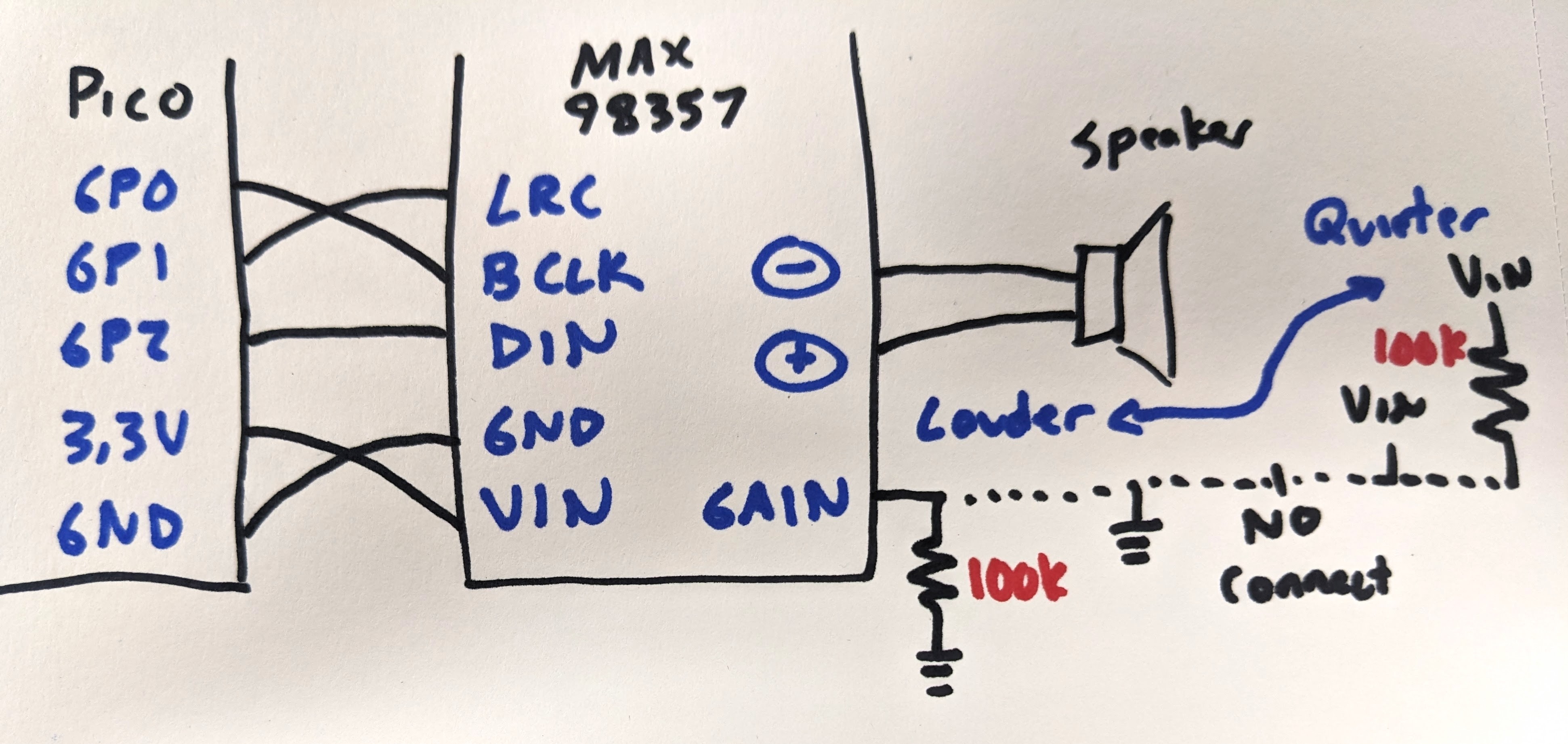
Play a sound with a digital amp
Humans can hear sounds from 20Hz to 20kHz. Sound is made by applying a varying signal to an amplifier to a speaker, sometimes as a voltage and sometimes digitally. The update rate effects the quality of the sound, and is required mathematically to be at least 2 times the highest frequency contained in the sample. But that means a lot of data needs to be stored and sent to the amplifier, so in microcontroller projects the quality is usually dropped in order to take up less space and computational time.
Here, a digital amplifier is used, the MAX98357, using a digital protocol called I2S. Digital transmission is nice because it helps to reject analog noise.
The following code plays a tone by making a sine wave with a specific frequency in an array. This type of sound is sometimes refered to as 8bit sound, although the data is actually 16bit in this case, and might remind you of "early Nintendo level" of sounds.
# play a tone

import time
import array
import math
import audiocore # library to play a sound
import board
import audiobusio # library to use I2S to communicate with MAX98357 amplifier

# for the MAX98357 amplifier
# Vin can be 3.3V or 5V, 5V is louder
# SD is shutdown if put to GND
# Gain: loudest with 100k to GND, loud straight to GND, regular no connection,
#       quieter straight to VIN, quietest 100k to VIN
audio = audiobusio.I2SOut(board.GP0, board.GP1, board.GP2) # I2S pins BCLK, LRC, DIN

tone_volume = 0.5  # digital volume, 0.0 to 1.0
frequency = 440  # tone frequency
samplerate = 8000
length = samplerate // frequency # // takes the floor() after doing the division
# make an array of signed 16bit values, which is what the MAX98357 takes
sine_wave = array.array("h", [0] * length) # the values are all initially 0

# make a single cycle of a sine wave to be played at 8kHz
for i in range(length):
    sine_wave[i] = int((math.sin(math.pi * 2 * i / length)) * tone_volume * (2 ** 15 - 1))
sine_wave_sample = audiocore.RawSample(sine_wave)

while True:
    audio.play(sine_wave_sample, loop=True)
    time.sleep(1)
    audio.stop()
    time.sleep(1)
You can also play a sound file, in .wav format. A .wav file has no compression, it is just a giant array of the signal recorded at a set frequency. Note the limited space on your microcontroller board, so you are limited in how long of a .wav file you can play. There are lots of sound editing softwares available to convert other file types into .wav, as well as downsample to lower frequencies to make the file smaller (try Audacity).
# play a .wav sound file
# copy the .wav file to the CIRCUITPY/ drive
# .wav file can be mono or stereo, <=22kHz sample rate, 16bit wav format, try the program Audacity to edit files
# note Pico W memory is 2Mbyte, so sound files need to be small
import audiocore
import board
import audiobusio
import time

wave_file = open("StreetChicken.wav", "rb") # from https://cdn-learn.adafruit.com/assets/assets/000/057/801/original/StreetChicken.wav?
wave = audiocore.WaveFile(wave_file)
audio = audiobusio.I2SOut(board.GP0, board.GP1, board.GP2) # MAX98357, I2S pins BCLK, LRC, DIN

while True:
    print("wav file start")
    audio.play(wave)
    while audio.playing:
        pass # code here that should only happen while wav is playing
    print("wav file done")
    time.sleep(3)
Play a sound with PWM
If you have an analog amplifier, you can play sound out of a PWM pin. It may have more hissing noise than a digital amplifier.
EAMPLE CODE HERE
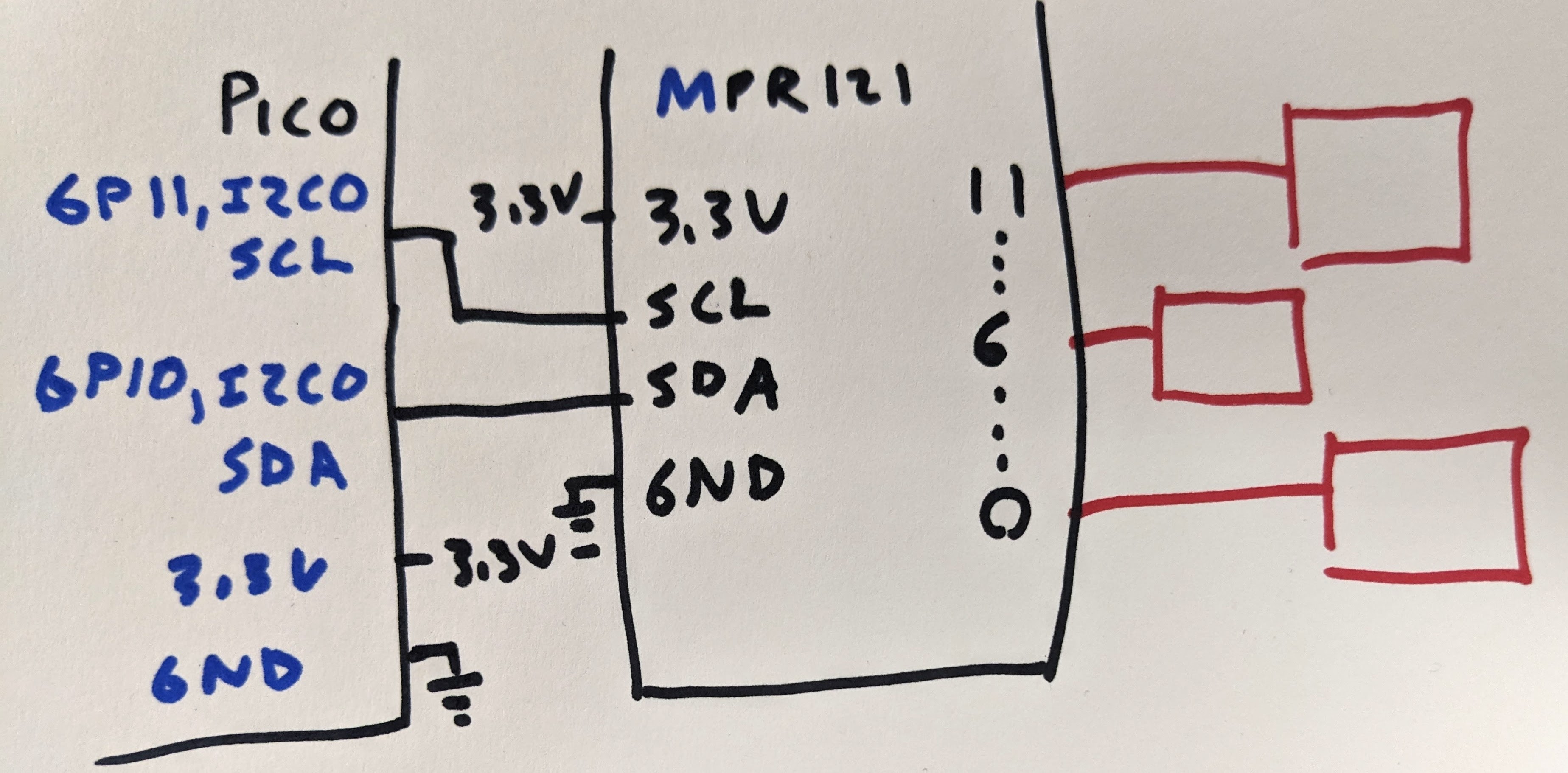
Read from a capacitive touch sensor
Physical buttons have limitations in certain environments, such as places that are dirty or wet. A "contactless" button can be made by reading the change in capacitance on a conductor when a user gets close to the surface. In this way the conductor can be placed behind a barrier and still detect presence. The downside to this technique is a lack of feedback in the form of a change in the force profile, like a detent, or an audible click, when the button is selected. The cool thing is that many nontraditional button materials can be used, as long as they a conductive (see bananna piano).
import time
import board
import busio

import adafruit_mpr121 # library for the MPR121 cap touch board

i2c = busio.I2C(board.GP11, board.GP10) # the I2C pins used, (SCL, SDA)
mpr121 = adafruit_mpr121.MPR121(i2c)

while True:
    # get the raw data from the pins
    pin0 = mpr121.filtered_data(0)
    pin6 = mpr121.filtered_data(6)
    pin11 = mpr121.filtered_data(11)
    # print in the format that the Plotter uses
    print("("+str(pin0)+","+str(pin6)+","+str(pin11)+",)")
    time.sleep(0.1)
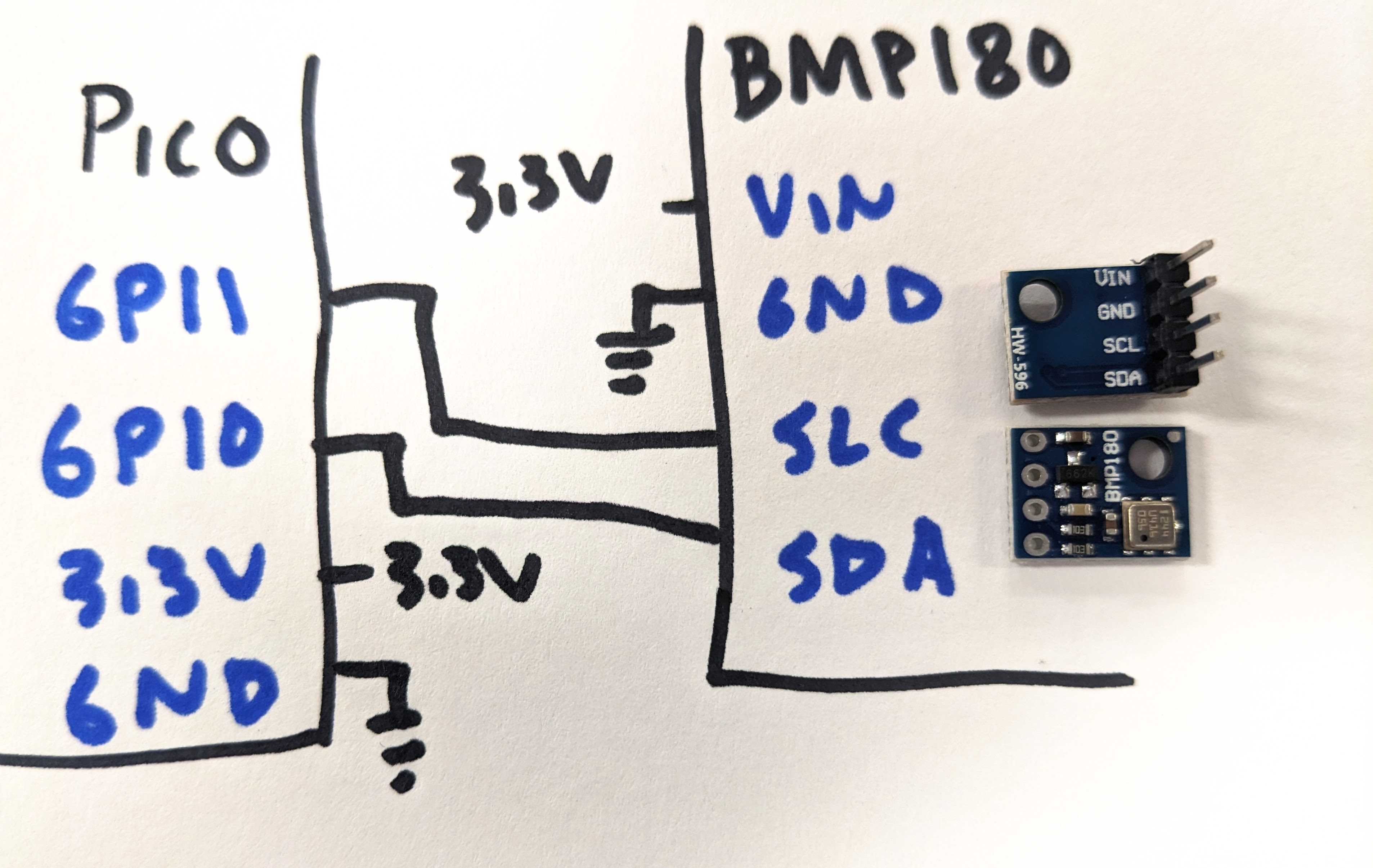
Read from a temperature and barometric sensor
The BMP180/BMP280 sensor returns temperature and air pressure measurements. The BMP180 resolution is not as good as the BMP280, but is otherwise the same. Barometric pressure can be used to estimate altitude or change in height, like going high up in a building.
# Read temperature and pressure measurements from the BMP180/280
import time
import board
import busio
import adafruit_bmp280

i2c = busio.I2C(board.GP11, board.GP10) # the I2C pins used, (SCL, SDA)
bmp280 = adafruit_bmp280.Adafruit_BMP280_I2C(i2c, address=0x77)

# change this to match the location's pressure (hPa) at sea level
bmp280.sea_level_pressure = 1013.25
bmp280.mode = adafruit_bmp280.MODE_NORMAL
bmp280.standby_period = adafruit_bmp280.STANDBY_TC_500
bmp280.iir_filter = adafruit_bmp280.IIR_FILTER_X16
bmp280.overscan_pressure = adafruit_bmp280.OVERSCAN_X16
bmp280.overscan_temperature = adafruit_bmp280.OVERSCAN_X2
# The sensor will need a moment to gather inital readings
time.sleep(1)

while True:
    print("\nTemperature: %0.1f C" % bmp280.temperature)
    print("Pressure: %0.1f hPa" % bmp280.pressure)
    print("Altitude = %0.2f meters" % bmp280.altitude)
    time.sleep(2)
Read from a laser proximity, gesture and light sensor
A more modern rangefinder uses the light reflected from a laser emitter, either from the ammount reflected or coherence. These sensors often can report other values, like ambient light conditions or gestures from waving in front of the sensor.

{{#include adps9930_proximity.py}}
Draw text to an I2C OLED monochrome display
OLED displays have very high contrast, with an LED for each pixel. Displays take a lot of memory and work best with SPI communication, but a small monochrome display can work with I2C which makes the wiring more convinient.

# draw text on the I2C OLED SSD1306 display

import time
import board
import busio
import adafruit_ssd1306
# also requires adafruit_framebuf
# requires a font file in .bin format to be in CIRCUITYPY/ from:
#   https://github.com/adafruit/Adafruit_CircuitPython_framebuf/blob/main/examples/font5x8.bin

i2c = busio.I2C(board.GP11, board.GP10) # the I2C pins used, (SCL, SDA)

display = adafruit_ssd1306.SSD1306_I2C(128, 32, i2c, addr=0x3C)

display.fill(0) # turn off every pixel in memory
display.show() # update the display

# use the following try..except block to make sure you have the font file
# once you know this works you can remove this section
try:
    display.fill(0)
    char_width = 6
    char_height = 8
    chars_per_line = display.width // 6
    for i in range(255):
        x = char_width * (i % chars_per_line)
        y = char_height * (i // chars_per_line)
        display.text(chr(i), x, y, 1)
    display.show()
    time.sleep(4)
    display.fill(0)
    display.show()
except FileNotFoundError:
    print(
        "Missing font file!"
    )
    while True:
        # no font file, get stuck here forever
        time.sleep()

i = 0
while True:
    display.fill(0) # turn off all pixels (fill(1) to turn on all pixels)
    display.text("i = "+str(i), 0, 10, 1) # write text to left corner at x,y,pixel on
    display.show()
    time.sleep(0.01)
    i=i+1
Draw an eye on a round TFT LCD
The GC9A01 is a driver for a 1.28 inch round TFT LCD display, controlled with SPI in 16bit color. The library is located in the Circuit Python Community Bundle, not the regular Library Bundle.

# display an eye with an iris that moves

import time, math, random
import board, busio
import displayio
import adafruit_imageload
import gc9a01

displayio.release_displays()

dw, dh = 240,240  # display dimensions

# load eye and iris bitmaps
# download from https://github.com/todbot/CircuitPython_GC9A01_demos/tree/main/examples/eyeballs/imgs
eyeball_bitmap, eyeball_pal = adafruit_imageload.load("images/Lizard_Sclera.bmp")
iris_bitmap, iris_pal = adafruit_imageload.load("images/Lizard_Iris_White.bmp")
iris_pal.make_transparent(244)

# compute or declare some useful info about the eyes
iris_w, iris_h = iris_bitmap.width, iris_bitmap.height  # iris is normally 110x110
iris_cx, iris_cy = dw//2 - iris_w//2, dh//2 - iris_h//2
r = 15  # allowable deviation from center for iris

tft0_clk  = board.GP10
tft0_mosi = board.GP11
tft_L0_rst  = board.GP12
tft_L0_dc   = board.GP13
tft_L0_cs   = board.GP14
spi0 = busio.SPI(clock=tft0_clk, MOSI=tft0_mosi)

# class to help us track eye info (not needed for this use exactly, but I find it interesting)
class Eye:
    def __init__(self, spi, dc, cs, rst, rot=0, eye_speed=0.5, twitch=1):
        display_bus = displayio.FourWire(spi, command=dc, chip_select=cs, reset=rst)
        display = gc9a01.GC9A01(display_bus, width=dw, height=dh, rotation=rot)
        main = displayio.Group()
        display.show(main)
        self.display = display
        self.eyeball = displayio.TileGrid(eyeball_bitmap, pixel_shader=eyeball_pal)
        self.iris = displayio.TileGrid(iris_bitmap, pixel_shader=iris_pal, x=iris_cx,y=iris_cy)
        main.append(self.eyeball)
        main.append(self.iris)
        self.x, self.y = iris_cx, iris_cy
        self.tx, self.ty = self.x, self.y
        self.next_time = time.monotonic()
        self.eye_speed = eye_speed
        self.twitch = twitch

    def update(self):
        self.x = self.x * (1-self.eye_speed) + self.tx * self.eye_speed # "easing"
        self.y = self.y * (1-self.eye_speed) + self.ty * self.eye_speed
        self.iris.x = int( self.x )
        self.iris.y = int( self.y )
        if time.monotonic() > self.next_time:
            t = random.uniform(0.25,self.twitch)
            self.next_time = time.monotonic() + t
            self.tx = iris_cx + random.uniform(-r,r)
            self.ty = iris_cy + random.uniform(-r,r)
        self.display.refresh()

# a list of all the eyes, in this case, only one
the_eyes = [
    Eye( spi0, tft_L0_dc, tft_L0_cs,  tft_L0_rst, rot=0),
]

while True:
    for eye in the_eyes:
        eye.update()
Read distance from an ultrasonic rangefinder
A classic way to estimate distance is to emit a pulse of sound and measure how long it takes for an echo to return. The sound is usually at 40kHz or above, outside the range of human hearing. Sound travels at 343m/s, so the distance can be calculated as the time, divided by two, times the speed of sound.
The HC-SR04 ultrasonic rangefinder is inexpensive, but works better with a 5V supply rather than the usual 3.3V. It can miss the echo or returns values with high amounts of noise, and has a wide view angle, so sometimes returns the distance of objects not exactly right in front of the sensor.
Here the library takes care of sending a pulse to the TRIG pin and timing how long the ECHO pin is high. Ocassionally the echo will not come back, so a "try: exception:" case is used to detect when there is no data.

# read from the hc-sr04 ultrasonic rangefinder
# works best with 5V from VBUS for VCC

import time
import board
import adafruit_hcsr04

sonar = adafruit_hcsr04.HCSR04(trigger_pin=board.GP16, echo_pin=board.GP17)

while True:
    try:
        print((sonar.distance,)) # in cm
    except RuntimeError:
        print("Retrying!")
    time.sleep(0.01)
Connect the Pico W to wifi and see the IP address
Your SSID and password can be kept outisde of code.py in the file settings.toml. Edit settings.toml with:
CIRCUITPY_WIFI_SSID = "your-ssid-here"
CIRCUITPY_WIFI_PASSWORD = "your-ssid-password-here"
This code will test to see if you can connect to the wifi network.
import os
import ipaddress
import wifi
import socketpool

print()
print("Connecting to WiFi")

#  connect to your SSID
wifi.radio.connect(os.getenv('CIRCUITPY_WIFI_SSID'), os.getenv('CIRCUITPY_WIFI_PASSWORD'))

print("Connected to WiFi")

pool = socketpool.SocketPool(wifi.radio)

#  prints MAC address to REPL
print("My MAC addr:", [hex(i) for i in wifi.radio.mac_address])

#  prints IP address to REPL
print("My IP address is", wifi.radio.ipv4_address)
Generate a website using the Pico W
Requires adafruit_httpserver folder to be added to CIRCUITPY/lib. This example will print the IP address. Go to that address/client, and the temperature of the Pico will be printed, and a color selector tool will return a color to the Pico and the Pico will generate that color on a Neopixel.
# set the color of a neopixel and see CPU temperature on a website
# go to the ipaddress/client in your browser
from time import monotonic # to set the update rate of the webpage
import board
import microcontroller # to read the temperature of the CPU
import neopixel
import socketpool
import wifi
from adafruit_httpserver import Server, Request, Response, Websocket, GET
pool = socketpool.SocketPool(wifi.radio)
server = Server(pool, debug=True)
pixel = neopixel.NeoPixel(board.GP15, 1)
websocket: Websocket = None
next_message_time = monotonic()
# this string contains an html website
# with a javascript function to allow the selection of a color
HTML_TEMPLATE = """
<html lang="en">
<head>
<title>Websocket Client</title>
</head>
<body>
<p>CPU temperature: <strong>-</strong>°C</p>
<p>NeoPixel Color: <input type="color"></p>
<script>
const cpuTemp = document.querySelector('strong');
const colorPicker = document.querySelector('input[type="color"]');
let ws = new WebSocket('ws://' + location.host + '/connect-websocket');
ws.onopen = () => console.log('WebSocket connection opened');
ws.onclose = () => console.log('WebSocket connection closed');
ws.onmessage = event => cpuTemp.textContent = event.data;
ws.onerror = error => cpuTemp.textContent = error;
colorPicker.oninput = debounce(() => ws.send(colorPicker.value), 200);
function debounce(callback, delay = 1000) {
let timeout
return (...args) => {
clearTimeout(timeout)
timeout = setTimeout(() => {
callback(...args)
}, delay)
}
}
</script>
</body>
</html>
"""
@server.route("/client", GET)
def client(request: Request):
return Response(request, HTML_TEMPLATE, content_type="text/html")
@server.route("/connect-websocket", GET)
def connect_client(request: Request):
global websocket # pylint: disable=global-statement
if websocket is not None:
websocket.close() # Close any existing connection
websocket = Websocket(request)
return websocket
server.start(str(wifi.radio.ipv4_address))
while True:
server.poll()
# Check for incoming messages from client
if websocket is not None:
if (data := websocket.receive(True)) is not None:
print(data) # print the message sent to the Pico
r, g, b = int(data[1:3], 16), int(data[3:5], 16), int(data[5:7], 16)
pixel.fill((r, g, b))
# Send a message every second
if websocket is not None and next_message_time < monotonic():
cpu_temp = round(microcontroller.cpu.temperature, 2)
websocket.send_message(str(cpu_temp))
next_message_time = monotonic() + 1